Freely Available British and Irish Public Legal Information
[Home] [Databases] [World Law] [Multidatabase Search] [Help] [Feedback]
England and Wales Court of Appeal (Civil Division) Decisions
You are here: BAILII >> Databases >> England and Wales Court of Appeal (Civil Division) Decisions >> Advanced Bionics Ag & Anor v Med-El Elektromedizinische Gerate GmbH [2023] EWCA Civ 637 (09 June 2023)
URL: http://www.bailii.org/ew/cases/EWCA/Civ/2023/637.html
Cite as: [2023] EWCA Civ 637
[New search] [Printable PDF version] [Help]
ON APPEAL FROM THE HIGH COURT OF JUSTICE, BUSINESS AND PROPERTY COURTS OF ENGLAND AND WALES, INTELLECTUAL PROPERTY LIST (ChD), PATENTS COURT
Campbell Forsyth sitting as a Deputy High Court Judge
Strand, London, WC2A 2LL |
||
B e f o r e :
LORD JUSTICE ARNOLD
and
LORD JUSTICE BIRSS
____________________
| (1) ADVANCED BIONICS AG (2) ADVANCED BIONICS UK LIMITED |
Claimants/ Respondents |
|
| - and - |
||
| MED-EL ELEKTROMEDIZINISCHE GERÄTE GMBH |
Defendant/ Appellant |
____________________
Andrew Lykiardopoulos KC and Edward Cronan (instructed by Kirkland and Ellis International LLP) for the Respondents
Hearing dates : 23-24 May 2023
____________________
Crown Copyright ©
- The Defendant ("Med-El") appealed with permission granted by myself against an order dated 21 September 2022 of Campbell Forsyth sitting as a Deputy High Court Judge revoking Med-El's European Patent (UK) No. 3 138 605 entitled "MRI-safe disk magnet for implants" ("the Patent") for the reasons given in the judge's judgment dated 1 June 2022 [2022] EWHC 1345 (Pat). As its title suggests, the Patent discloses and claims a cochlear implant which comprises a magnet that makes the implant safer in MRI scanners than prior implants. There was no challenge to the claimed priority date of 23 April 2010. The judge held that the Patent was obvious in the light of Med-El's International Patent Application No. WO 03/081976 entitled "Reducing effect of magnetic and electromagnetic fields on an implant's magnet and/or electronics" ("Zimmerling"); but that, if the Patent had been valid, the Claimants ("Advanced Bionics") would have infringed it by dealings in their HiRes Ultra 3D cochlear implant device. Advanced Bionics contended by a respondents' notice that, if the Patent was valid, they had not infringed it.
- After the judge's judgment and order, the Patent was maintained in amended form by the Technical Board of Appeal of the European Patent Office in decision T 732/21 dated 28 September 2022 for reasons given in writing on 12 December 2022. It was common ground on the hearing of the appeal that: (i) this Court had to consider the Patent as so amended; (ii) the amendments made no difference to the obviousness issue; and (iii) the amendments made no difference to the infringement issue considered by the judge, but gave rise to an additional issue which could and should be considered by this Court.
- At the conclusion of the argument on obviousness, the Court announced that the appeal would be dismissed for reasons to be given in writing later. It followed that it was unnecessary to hear argument on infringement. My reasons for concurring in that disposition of the appeal are as follows.
- It is common ground that the Patent is addressed to a team consisting of a biomedical engineer with experience in designing cochlear implants and a clinician specialising in otolaryngology and neurotology.
- Each side called two expert witnesses, a biomedical engineer and a clinician. Little turns on the evidence of the clinicians. Med-El's biomedical engineering expert was Professor Gregg Suaning while Advanced Bionics's biomedical engineering expert was Professor John Parker. The judge found Prof Parker at [21] and [31] to be "an extremely open and helpful expert", "a good educator for the court" and "a fair witness" who "came across as keen to assist, educate and willing to make concessions as appropriate". The judge rejected at [22]-[31] and [223]-[233] criticisms advanced by Med-El that Prof Parker had failed properly to consider the issue from the perspective of the skilled person and that his approach had been tainted by hindsight. By contrast, the judge found Prof Suaning at [20] to be at times "too controlled and overly careful in his answering questions to the point it came across as slightly partisan to the Med-El case", although "a good educator for the court" who "made sensible concessions as appropriate". More specifically, the judge's assessment of Prof Suaning's evidence as to whether it was common general knowledge that a diametrically magnetised permanent magnet could rotate when interacting with an external magnetic field was that some of his responses "appeared blinkered" and at times he "came across as trying to justify his positions rather than answering the questions" ([49]); and the judge's assessment of Prof Suaning's evidence as to the teaching of Zimmerling was that "[h]is answers could come across as evasive and at times contradictory" ([213]).
- The judge appended to his judgment as Annex B an agreed statement of common general knowledge prepared by the parties. The judge made findings as to certain disputed areas at [40]-[63]. The common general knowledge which is relevant to the appeal can be summarised as follows.
- Permanent magnets have a magnetic moment which describes the strength and orientation of the magnetic field of the magnet. This is called the magnetic dipole. It is a vector quantity (it has direction). The magnetic fields of two magnets (whether permanent or electromagnetic) will interact with one another. The force induced from that interaction (called torque) will depend on the shape and strength of the magnetic fields. The force is proportional to the magnetic field strength and inversely proportional to the square of the distance between the magnets. The tesla ("T") is the standard unit for magnetic flux density – a measure of the strength of a magnetic field.
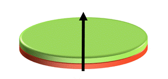
- Magnets were available in 2010 in any reasonable basic shape and they could be magnetised in a variety of different ways. Axially magnetised permanent magnets have their magnetic dipole positioned in the axial direction as schematically shown below (with green denoting the north pole and red the south pole) for a disk-shaped magnet.
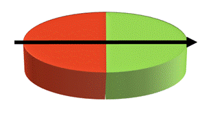
- Diametrically magnetised permanent magnets have their magnetic dipole positioned across their face as schematically shown below. The diagram again shows a disk-shaped magnet as an example, but the principle is of general application. In the case of a spherical magnet, whether it is considered diametric or axial would depend on its orientation.
- A diametrically magnetised permanent magnet can rotate when interacting with an external magnetic field. A common example of this is a magnetic stirrer of the kind used to stir liquids in laboratories, in which a diametrically magnetised permanent magnet shaped like a cylinder is caused to rotate about an axis perpendicular to the cylinder by an external magnetic field.
- A cochlear implant is a small electronic device that assists a person who is profoundly deaf or hard of hearing to perceive sound. One part – the external component – is placed on the skin behind a person's ear, while another part – the internal component – is surgically implanted under the skin. The implant works by directly stimulating the neural tissue within the cochlea with electrical pulses, thus bypassing damaged portions of the inner ear. The implant's signals are sent to the brain, which recognizes the signals as sounds.
- The internal component contains an RF receiver coil, a processor, a flexible electrode array, a permanent magnet and optionally a ground electrode. The external component comprises a microphone, speech processing electronics, a battery, an RF coil to transmit sound and power to the internal component and a magnet. The internal component is intended to last for the lifetime of the patient, whereas the external component can be replaced if it is damaged or when more advanced products become available.
- The surgery to implant the internal component is usually performed under general anaesthesia. A small incision is made behind the ear. It is then necessary to perform a mastoidectomy (open the hollow, air-filled spaces in the skull behind the ear) to gain access to the facial recess. The processor component is placed posteriorly through the skin incision, so it lies over the skull behind the mastoid bone. A pocket may be drilled in the skull to recess some of the device and the lead that goes to the electrode. In some cases, a larger recessed area can be made in the bone that includes the posterior aspect of the implant including the receiver coil, of the internal component to sit in. This larger recessed area requires more exposure and often a bigger incision. Devices being implanted in 2010 were generally thinner than earlier devices, however, and did not generally require bone drilling for the posterior aspect of the implant including the receiver coil and the magnet.
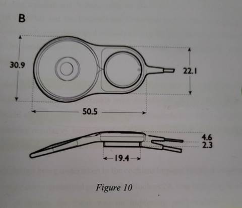
- In 2010 there were three major suppliers of cochlear implants: Advanced Bionics, Med-El and Cochlear. By that date the designs of the internal components of commercial cochlear implants had converged into a flat, thin and planar coil housing (containing the receiver coil, a disk-shaped magnet in the middle of the coil and a silicon chip for sound processing) and a section containing additional electronics which was also flat and of broadly similar depth. The two elements were angled to each other in order to conform to the curve of the skull, as shown below.
- In 2010 the external component typically had two parts: a part that sat behind the ear and a puck-shaped part containing the RF coil that sat on the skin over the corresponding RF coil of the internal component. The puck-shaped part was held in place by magnetic attraction between the magnet in the middle of the RF coil in the internal component and a magnet in the middle of the RF coil in the puck-shaped part of the external component. The magnets also ensured appropriate alignment of the internal and external RF coils. The magnets of the internal and external components were both axially magnetised and their magnetic dipole was perpendicular to the skin.
- Design considerations for the internal component of cochlear implants at the priority date in addition to auditory performance included a low profile, reliability, regulatory compliance, suitable attachment magnet strength and compatibility with external devices such as MRI scanners.
- Magnetic resonance imaging ("MRI") is a non-invasive diagnostic technique in which a strong magnetic field is used to scan and image soft tissues. The number of MRI machines in use had risen between 2000 and 2010. MRI systems are classified by the strength of the static magnetic field. In 2010 the most common MRI machines in clinical use were 1.5T, but 3T machines were becoming more common.
- There are two major types of MRI machines in clinical use: closed bore machines and open systems. Closed bore machines employ a donut-shaped magnet system and the patient is passed through the centre of the donut. When the patient is placed into the bore, the magnetic field lines are aligned along the length of the patient from head to toe. Open systems are open on three to four sides depending on manufacturer and model. The magnetic strength in these machines is significantly lower than in closed bore machines. Open systems typically have their magnetic fields aligned vertically rather than horizontally as in closed bore machines.
- A number of problems and potential hazards arise when ferromagnetic or magnetic material is placed in a strong magnetic field, such as the introduction of the internal component of a cochlear implant into an MRI machine. The external component could, of course, easily be removed by the wearer for an MRI scan, but not the internal component.
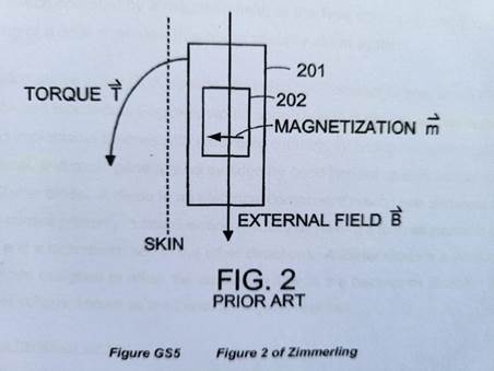
- One problem which was well known in 2010 was that the internal axially magnetised disk-shaped permanent magnet of a cochlear implant would, when in close proximity to the external magnetic field of an MRI machine, experience torque. This torque could cause the implanted magnet and its housing to be dislocated, causing improper function of the device, and pain and potentially tissue damage to the patient. This is illustrated by the diagram reproduced below, which is Figure 2 of both Zimmerling and the Patent. It shows the external MRI field B interacting with the magnetisation of the permanent magnet 202. The field lines are perpendicular to each other. The torque created by the interaction is shown by the arrow indicating the rotation of the implant 201 containing permanent magnet 202. The precise strength of the torque will depend on the interaction of the respective magnetic fields.
- Prior to 2010 the main solutions to this problem that had been adopted were either to surgically remove the internal component or its magnet (if the latter was designed to be removable) or tightly to wrap the head of the patient. Surgery was undesirable and wrapping not wholly effective.
- Zimmerling was published on 9 October 2003. The following summary of the disclosure is largely based on the judge's summary at [191]-[204]. Like the judge, I shall adopt the headings in the specification.
- The abstract begins by explaining that Zimmerling discloses an "implantable magnet that can freely turn in response to an external magnetic field, thus avoiding torque and demagnetization on the implantable magnet". This implantable magnet "can be combined with an electric switching function depending on the orientation of an external magnetic field".
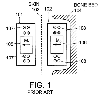
- This section of Zimmerling describes a prior art cochlear implant system shown in Figure 1 reproduced below.
- This shows the internal component of a cochlear implant 102 under the skin, with its magnet 106. The external magnet 105 is shown as positioned over the internal magnet.
- Zimmerling describes how, when a patient with a cochlear implant has an MRI scan, interactions between the implanted magnet and the external MRI magnetic field may at higher field strengths (above about 1T) produce two harmful effects. The first problem is that, as shown in Figure 2 (reproduced in paragraph 20 above), the implanted magnet may experience torque that can twist the magnet and the implant out of position, potentially injuring the wearer. The second problem is that, due to the strong external magnetic field, the implanted magnet may become partly demagnetised and therefore not be strong enough to hold the external component in place.
- Zimmerling goes on to identify further problems: RF pulses emitted by the MRI unit may induce voltages in the implant coil or circuit which may damage the circuitry; and artifacts may appear in the MRI image, caused by the local magnetic field of the implanted magnet, which distorts the homogeneous MRI field.
- Zimmerling describes some ways these issues could be avoided: avoiding MRI scans with strong fields, but this may exclude the patient from important diagnostic examinations; and implanting magnets which can be removed and re-inserted for an MRI scan, but this approach has the downside that a patient has to undergo surgery. Other alternatives noted are to use identical implant magnets with opposite orientation or to use a magnetically soft material.
- At page 2 line 29 – page 3 line 13 Zimmerling describes a first embodiment of the invention in which a magnetic switch is provided. The switch is responsive to an external magnetic field. This aspect of Zimmerling utilises the rotation of the internal magnet in an external magnetic field to provide protection from RF overvoltages.
- At page 3 lines 14–27 Zimmerling describes a second embodiment in which the implant includes a housing and "[a]t least one magnet is free to turn in the housing such that the at least one magnet is capable of aligning at least partially with an external magnetic field." Although not expressly mentioned here, the skilled team would understand that this reduces torque, as stated in the abstract. Zimmerling goes on to say:
- At page 4 line 30 – page 5 line 2 Zimmerling repeats that, in an embodiment of the invention, "the magnet is free to rotate such that the magnet is capable of aligning at least partially with an external magnetic field", and that the magnet may be spherical or cylindrical.
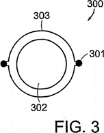
- As described at page 7 line 20 – page 8 line 5, Figure 3 (reproduced below) shows an implant 300 which includes a magnet 302 that is held in the implant "in such a way that the magnet can turn into the direction of an externally applied magnet field" so that it "does not experience any torque". The magnet 302 may be enclosed in a housing 303. The housing allows the magnet "of whatever shape to turn, possibly with some restrictions, into the external magnetic field lines". As shown in Figure 3, magnet 302 is "a spherical magnet that is free to turn in any direction".
- Zimmerling goes on to say at page 8 lines 6-19:
- It is not in dispute that the skilled biomedical engineer would understand that the statement that the "cylindrical magnet carries a magnetization … normal to its axis" means that the magnet is diametrically magnetised.
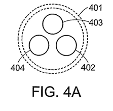
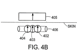
- Page 8 line 20 – page 9 line 2 describes by reference to Figures 4A and 4B an embodiment with three, smaller spherical magnets 402-404. This arrangement allows for a "thinner design of the implant". These magnets may be arranged "some distance apart from each other, thus facilitating the orientation of magnets 402-404 primarily along the field lines of an external holding magnet 405".
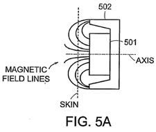
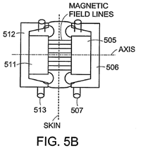
- Page 9 lines 3-17 describes by reference to Figures 5A and 5B an embodiment in which implanted magnet 501 is partially surrounded by magnetically soft material 502 which creates a low reluctance path for magnetic flux. This is said to partly shield the magnet 501 from the external magnetic field, reducing both the torque and demagnetization of magnet 501 to a large extent.
- Page 9 line 18 – page 10 line 2 describes by reference to Figures 6A and 6B embodiments using a ferrofluid as the implanted magnet. A ferrofluid is a liquid-state material which contains tiny magnetic particles suspended in a fluid. This magnet can magnetize in the direction of an external magnetic field and experience no torque in an MRI. It will also not demagnetize. However, to get the required holding force for attachment the volume of the implanted magnet may have to be comparatively larger.
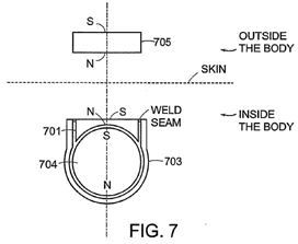
- Page 10 lines 3-21 describes by reference to Figure 7 an embodiment in which a "low-reluctance part" is added to improve magnetic flux between the implanted magnet and the external magnet and/or to shield magnetic field lines facing towards the inner side of the body, to minimize magnetic resistance and imaging artifacts.
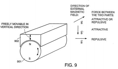
- Page 12 lines 18-29 describes by reference to Figure 9 an embodiment in which permanent magnet 901 is a cylinder which is "free to turn around its rotational axis". As Zimmerling explains:
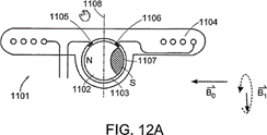
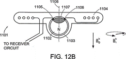
- Page 13 line 20 – page 14 line 15 describes by reference to Figures 11, 12A and 12B an embodiment with a spherical magnet 1102 in an implant 1101. The rotational symmetry axis 1108 of the implant 1101 may be oriented perpendicular (Figure 12A) or parallel (Figure 12B) to the main magnetic field B0 of an MRI scanner.
- The Patent shares an inventor with Zimmerling. The judge accurately summarised the specification at [64]-[78]. For present purposes it is not necessary to repeat all of that summary, and the following will suffice.
- The specification at [0002] discusses by reference to Figure 1 prior art cochlear implant systems in which the external magnet 103 has a "conventional coin-shape and a north-south magnetic dipole that is perpendicular to the skin of the patient to produce external magnetic field lines" and the internal magnet 107 "also has coin-shape and a north-south dipole that is perpendicular to the skin of the patient to produce internal magnetic field lines". The external transmitter housing 101 is placed over the skin covering the internal receiver assembly 105 and held in place by the interaction between the internal magnetic field lines 108 and the external magnetic field lines 104.
- The specification goes on in [0003] to discuss the problem of torque in an MRI scanner by reference to Figure 2 reproduced in paragraph 20 above. The torque may displace the internal magnet or the whole implant housing out of proper position and this may damage adjacent tissue in the patient. In addition, the MRI field may reduce or remove the magnetisation of the implant magnet. It may also cause imaging artifacts in the MRI image and may induce voltages in the receiving coil, and hearing artifacts due to the interaction of the external magnetic field of the MRI with the implanted device.
- Prior art solutions to this problem are discussed in [0004]-[0006], including Zimmerling. The specification says that the spherical magnet design may be the most convenient and safest option, but it requires a relatively large magnet which is much larger than the thickness of the other components of the implant, thereby increasing the volume occupied by the implant.
- The invention is summarised in [0007]. It is directed to an implant system. A "first attachment magnet is located within the plane of the coil housing and rotatable therein (e.g. a planar disk shape) and has a magnetic dipole parallel to the plane of the coil housing for transcutaneous magnetic interaction with a corresponding second attachment magnet". The first attachment magnet is the internal magnet and the second attachment magnet is the external magnet.
- Further embodiments are described at [0008]-[0009]. The invention is described in more detail in [0010]:
- In [0013] the specification compares the axial magnetic dipole in typical existing disk-shaped implant attachment magnets shown in Figure 3A with the magnetic dipole oriented across the diameter of the magnet parallel to the plane of the coil housing shown in Figure 3B in an attachment magnet according to the invention.
- The specification goes on in [0014] to explain that it is important that both the internal implant receiver attachment magnet and the external transmitter attachment magnet are magnetised in the same orientation in the plane of the coil housing (i.e. parallel to the skin). Then when the external coil housing is placed onto the patient's skin over the implant coil housing the two attachment magnets turn around their axis so that the north and south poles of one attachment magnet are adjacent to the south and north poles of the other attachment magnet to maximise the attractive magnetic forces.
- The specification describes a cochlear implant according to the invention in [0015] by reference to Figures 4A and 4B. Figure 4A shows an elevated perspective view and Figure 4B shows a side cross-sectional view of a cochlear implant 400 having a planar coil housing 402 that contains a signal coil for transcutaneous communication of an implant communication signal. It goes on to describe the rest of the system. A first attachment magnet 401 is located within the plane of the coil housing 402 and rotatable therein (e.g. a planar disk shape) and has a magnetization direction with a magnetic dipole parallel to the plane of the coil housing 402. An external transmitter coil housing 405 has a corresponding second attachment magnet 404 with a similar magnetic dipole direction parallel to the plane of its coil housing 405 so that when placed on the skin of the recipient patient, their respective magnetic fields cause the two attachment magnets 401 and 404 to self-orient as described above to form a magnetic attraction connection between them.
- The specification goes on in [0016] to describe how the patient will use an embodiment when undergoing an MRI. It recognises that, as the patient is brought into the MRI scanner, the attachment magnet may have a component of its magnetization which is perpendicular to the external magnetic field of the scanner. This will result in the attachment magnet turning around on its axis to align the magnetization direction of its magnetic dipole with the static field of the MR scanner. This effect occurs with MRI scanners with both closed and open bores.
- The specification explains in more detail at [0017] what happens if the attachment magnet cannot completely align with the external static magnetic field. It explains that there will be a reduction in torque and a low risk of weakening of the attachment.
- The specification describes various embodiments at [0018]-[0024]. At [0022] it notes that, although the embodiments described in the earlier paragraphs are disk-shaped, any shape could be implemented so long as the magnetisation is parallel to the coil housing and the skin. It is explained that, as well as attachment magnets that have a magnetisation axis that is perpendicular to the rotational axis of the disk as set out in the earlier embodiments, in other embodiments the attachment magnets may more generally have a magnetisation axis that is not parallel to the rotational axis.
- The specification compares the invention with spherical magnet designs at [0026]:
- Further benefits of the invention are explained at [0027]-[0028].
- The claims in issue before the judge were claims 1 and 10 as granted and claim 14 as unconditionally proposed to be amended. Since the judge found claim 1 valid, he did not need to consider whether claims 10 and 14 were independently valid. Claim 1 as maintained by the Board of Appeal incorporates both the additional feature of claim 10 and a feature (integer [6] below) which was not present in any of the granted claims. Omitting reference numerals and broken down into integers, it reads as follows:
- The judge considered what Zimmerling would teach the skilled team at [205]-[215]. Having noted at [205] that there was little difference between the experts about this, and that the dispute mainly focussed on what the biomedical engineer would do in the light of the teaching, he summarised the teaching of Zimmerling at [206] as follows:
- As the judge went on to note, it was common ground that the magnetic switch would not be of interest to the skilled team in 2010. By contrast, as he noted at [222], it was common ground that Zimmerling's use of rotatable implant magnets would be of interest as an approach to overcoming the problem with MRI compatibility.
- The judge considered the teaching of Zimmerling with regard to rotation and orientation of the magnets in more detail in the following passages:
- It is convenient to note at this juncture that, during the course of argument over the form of order, the judge acknowledged that the second sentence of [215] contained an error. The judge suggested that what he had meant to say was that the "dipoles", rather than "axis of rotation", were perpendicular to the skin. As counsel for Med-El submitted, that suggestion does not make much technical sense in context. Counsel for Advanced Bionics suggested that what the judge must have meant to say was "parallel" to the skin rather than "perpendicular". Read in that way the sentence makes better sense.
- The judge identified the differences between Zimmerling and the claimed invention at [220] as follows:
- The judge added at [221]:
- At [223]-[233] the judge considered and, as I have noted above, rejected Med-El's criticism of Prof Parker's evidence as being tainted by hindsight. He concluded at [233] by quoting from the following paragraph in Prof Parker's expert report:
- At [234] the judge said that he was conscious in particular of the need to be careful when considering inventions that look simple in hindsight.
- The judge considered whether the claimed invention was obvious in the light of Zimmerling at [237]-[263]. His reasoning can be summarised as follows. He began at [239] by noting that Prof Suaning's evidence was that the skilled engineer would focus on the specific embodiments of Zimmerling, and in particular the Figure 4 embodiment, whereas Prof Parker's evidence was that the skilled engineer would be more interested in the general teaching of Zimmerling.
- At [240] the judge quoted from a paragraph in Prof Parker's second report:
- At [242] the judge considered a series of steps which Prof Suaning postulated would be required to get from Zimmerling to the claimed invention. For present purposes it is only necessary to set out the judge's comments on two of these steps:
- Having discussed Prof Suaning's evidence about Figure 4 of Zimmerling, the judge went on at [246]:
- At [250]-[260] the judge considered Med-El's case that there had been a long-felt want for a solution to the problem of MRI compatibility which the invention had solved but Zimmerling had not. After citing, among other authorities, Halliburton Energy Services Inc v Smith International (North Sea) Ltd [2005] EWHC 1623 (Pat), [2006] RPC 2 at [172] (Pumfrey J), he said at [257]:
- Having discussed the evidence at [258]-[259], the judge reached the following conclusion on this sub-issue at [260]:
- The judge expressed his overall conclusion as follows:
- Obviousness involves a multi-factorial evaluation, and therefore this Court is not justified in intervening in the absence of an error of law or principle on the part of the judge: see Actavis Group PTC EHF v ICOS Corp [2019] UKSC 15, [2019] Bus LR 1318 at [78]-[81] (Lord Hodge). This accords with the general approach of this Court to appeals against evaluative decisions: see Re Sprintroom Ltd [2019] EWCA Civ 932, [2019] BCC 1031 at [72]-[78] (McCombe, Leggatt and Rose LJJ).
- Med-El's grounds of appeal are as follows. Ground 1 is that the judge "erred in principle by failing to appreciate that a core part of the invention of the Patent was to redefine the problem which was addressed by the prior art". Ground 2 is that the judge "erred in principle in failing to appreciate the role that hindsight played in accepting a path to obviousness consisting as [sic] discrete steps which would not, and could not, have been taken without prior knowledge of the ultimate multi-faceted solution presented by the Patent". Ground 3 is that, "had the judge correctly understood multi-faceted nature of the invention that required insight as to the final solution, he would have appreciated Med-El's expert's reluctance to accept the stepwise approach being pressed upon him in cross-examination. Having failed so to appreciate, the judge wrongly criticised Med-El's expert and afforded his evidence insufficient weight". Ground 4 is that the judge "erred in law by requiring that Med-El show that the entire industry knew of the prior art to support a case of long-felt want. Had [the judge] not so erred, he would have found that the secondary evidence supported a finding of inventive step".
- I have quoted the grounds of appeal verbatim because, in some respects, counsel for Med-El's submissions did not accord with those grounds.
- Grounds 2 and 3 are really two sides of the same coin, and amount to a contention that the judge erred in principle because he failed to apply Lord Diplock's well-known warning in Technograph Printed Circuits Ltd v Mills & Rockley (Electronics) Ltd [1972] RPC 346 at 362. This is not a promising contention given that: (i) the judge cited at [249] Fletcher Moulton LJ's equally well-known earlier warning to much the same effect in British Westinghouse Electric and Manufacturing Company Ltd v Braulik (1910) 27 RPC 209 at 230; (ii) the judge explained in detail at [242] why he was not persuaded by Prof Suaning's evidence as to the multiplicity of steps required to reach the invention; and (iii) the judge's analysis only involved two (or at most three) steps: substituting a diametrically magnetised disk-shaped magnet for the spherical or cylindrical internal magnet proposed in Zimmerling and then adopting a matching external magnet. In any event, this contention was not pursued in argument.
- Instead, the principal ground of appeal pursued by Med-El in argument was that the judge had erred in principle because he had isolated teaching from Zimmerling at too high a level of abstraction and shorn of important detail in the document which provided context and purpose. I will call this ground 0. Counsel for Advanced Bionics rightly raised no objection to this ground being advanced, since it was clearly foreshadowed in Med-El's skeleton argument even if not in its grounds of appeal.
- Counsel for Med-El relied upon the principle stated by Floyd J in Ratiopharm GmbH v Napp Pharmaceutical Holdings Ltd [2008] EWHC 3070 (Pat), [2009] RPC 11 at [158]:
- On its face, this principle is not applicable to an item of documentary prior art such as Zimmerling. Counsel nevertheless submitted that it was applicable by analogy. I disagree: it depends on the prior art in question and on the evidence. For example, the evidence may show that the skilled person or team would only be interested in one aspect of the prior art and not in other aspects. Indeed, as noted above, it is common ground that this is true of Zimmerling itself: the skilled team would not be interested in the magnetic switch disclosed by Zimmerling, but would be interested in the disclosure of rotatable internal magnets. Nevertheless, I would accept that it would be an error of principle for a judge to extract a general teaching from an item of prior art divorced from its context and purpose if that general teaching was not disclosed in the document and would not be discerned by the skilled reader.
- In the present case it cannot be said that the judge ignored the detail in Zimmerling, since he set out a succinct but comprehensive summary of all the relevant parts of the disclosure. Counsel for Med-El submitted that the judge had nevertheless made an error of principle when he came to consider what Zimmerling would teach the skilled team.
- Counsel for Med-El argued that the error in the judge's approach was encapsulated in his statement in [206] that the second solution taught by Zimmerling was that "the implant magnets can rotate to align with an external magnetic field". Zimmerling disclosed much more than this, and stated at that level of generality this was a statement of the problem of torque caused by the rotation of an implanted magnet in an external magnetic field and not of Zimmerling's solution to that problem. Rather, what Zimmerling disclosed was the idea of making the internal magnet a shape which allowed rotation of the magnetic dipole away from the position that it was intended to take when in use. In use the dipole remained perpendicular to the skin, but the magnet could temporarily rotate the dipole away from that direction under the influence of the external field of the MRI. Moreover, Zimmerling did not change the external magnet.
- I do not accept this argument. The issue is partly one of interpretation of Zimmerling and partly one of what the skilled engineer would take from it. So far as the interpretation of Zimmerling is concerned, the judge was correct. As noted above, Zimmerling states in the abstract that it discloses an "implantable magnet that can freely turn in response to an external magnetic field, thus avoiding torque". Furthermore, Zimmerling twice states in the summary of the invention that the magnet is "free to turn/rotate" so that it is "capable of aligning at least partially with an external magnetic field". This is clearly general teaching not limited to the specific embodiments which follow. If confirmation of this were needed, it is provided by the fact that claim 13 is expressed at the same level of generality. Still further, although it is true to say that the only specific shapes disclosed by Zimmerling are spheres and cylinders, Zimmerling is at pains to say that these are not limiting and that a variety of shapes may be utilised. Finally, Zimmerling discloses a cylindrical magnet which is diametrically magnetised. Thus it is clearly not limited to axially magnetised internal magnets.
- As for what the skilled engineer would take from Zimmerling, the judge's finding reflected common ground between the experts. Prof Parker stated in his first report that Zimmerling's "main teaching is the idea of permitting the implant magnet to rotate, such that it can align at least partially with the MRI field". Similarly, Prof Suaning stated in his first report under the heading "What the Skilled Biomedical Engineer would do in light of Zimmerling":
- Counsel for Med-El also argued that the same error pervaded the judge's analysis at [208], [211]-[212] and [214]-[215]. The points he made are no better than the ones concerning [206], but nevertheless I will deal with them briefly.
- Counsel criticised [208] for two reasons. First, Zimmerling did not describe the sphere as the perfect shape. This is precisely why the judge put the word "perfect" in inverted commas. Secondly, any shape of magnet can fully align with an external magnetic field: the point about a sphere is the only shape that rotate in any direction within the same volume of space. That is clearly what the judge meant.
- Counsel criticised [211] on the basis that the judge had wrongly linked Zimmerling's teaching that a variety of different shapes could be used with its teaching about varying the orientation of the axis of the cylinder by up to 45o. In fact, the judge separated the two statements by the word "[a]lso". But in any event the statements are linked, in the sense that the teaching about the cylinder does not apply to the sphere as the judge explained.
- Counsel criticised [212] on the basis that Zimmerling did not "teach" using external axially magnetised magnets since that was conventional. This is purely semantic point. A prior art document can teach the reader something that is conventional.
- Counsel criticised [214] for suggesting that Zimmerling taught "changing the orientation of the magnetic dipole to one that is across the axis of rotation allows the magnet to turn". This was wrongly put as a general point not specific to any particular shape, and wrongly imported the idea of changing the dipole. As the judge said, however, Prof Suaning accepted that the cylindrical magnet in Zimmerling was diametrically magnetised. Furthermore, that does represent a change from the axial magnetisation of the conventional disk-shaped magnets.
- Counsel criticised the first sentence of [215] as an unjustified generalisation. I do not accept this: it is a summary of the points made in the preceding paragraphs. As the judge recognised, in the case of spheres, both the direction of the dipole and the axis of rotation depend on the orientation; but that does not detract from the judge's summary. Counsel also pointed out that the second sentence of [215] contained an error, but I have dealt with that above.
- This ground of appeal depends on the contention that a core part of the claimed invention was to redefine the problem addressed by the prior art (i.e. Zimmerling). Counsel for Med-El made little attempt either in his skeleton argument or his oral submissions to make that contention good, however. This is not surprising given that Zimmerling and the Patent address precisely the same problem, and even use the same figure to illustrate that problem. Furthermore, it can be seen from Zimmerling and from the Patent that both solutions involve rotation of the internal magnet when exposed to the external magnetic field in an MRI scanner. Med-El's argument before the judge, which was supported by Prof Suaning's evidence, was that the invention depended upon a "eureka moment", namely the insight that one could "flip the dipole" of a conventional disk-shaped magnet from axial to diametric. The problem facing Med-El on the appeal is that the judge confronted this argument head-on and gave reasons supported by the expert evidence for not accepting it.
- In reality, the submissions advanced by counsel for Med-El in support of this ground were arguments that the judge had reached the wrong conclusion in his assessment of obviousness, not that he had made any error of principle. Nevertheless, I shall deal briefly with them.
- Counsel criticised the judge's identification of the differences between Zimmerling and the claimed invention at [220] on the basis that "[w]hat the judge has identified as the difference is [in] fact the Patent's key contribution". This is a baffling criticism. It is usually the case that a patent's key contribution lies in the difference between the claims and the prior art. That does not alter the fact that the court's task is to ask whether the step from the prior art to the claims was an obvious one.
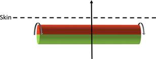
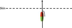
- Counsel criticised [221] as having all the hallmarks of hindsight. I do not accept this. The top diagram illustrates the Zimmerling cylinder magnet. The bottom diagram illustrates the internal magnet in the claimed invention, which is a diametrically magnetised disk-shaped magnet oriented parallel to the skin. As the judge explained, the middle diagram shows a diametrically magnetised disk-shaped magnet oriented perpendicular to the skin. One could understand the charge of hindsight if the judge had suggested or implied that the middle diagram provided a conceptual stepping stone from the top to the bottom, but in fact the judge was careful to say that this was not how the skilled person would think.
- Counsel criticised the judge's reasoning in [242](c), and in particular his statement that Prof Suaning had accepted that "this type of rotation was taught by Zimmerling". This statement needs to be read in context. The context is that the judge is considering Prof Suaning's evidence that "no-one was thinking about rotating". Read in that context, it seems to me that the point the judge is making is that, not only does Zimmerling teach rotation of an internal magnet in an MRI field, but more specifically it teaches rotation of a diametrically magnetised magnet (something that was also common general knowledge). The judge accepts that Zimmerling does not suggest using a flat disk-shaped magnet.
- Perhaps most importantly, counsel criticised [246] on the basis that the first step was to decide to use a disk-shaped magnet. Counsel argued that this amounted to a decision to throw away the entirety of Zimmerling's teaching with respect to the rotatable magnets and to do something entirely different. I do not accept this argument. The judge gave solid reasons, which he summarised in [263], for concluding that it would be obviously desirable to retain the conventional disk-shaped magnet and housing oriented parallel to the skin. This would not involve throwing away Zimmerling's teaching about using a rotatable magnet to align with the external magnetic field in an MRI scanner. On the contrary, as discussed above, Zimmerling is clear that a variety of shapes may be utilised. In those circumstances it was open to the judge to conclude that it would be obvious to apply Zimmerling's teaching to a disk-shaped magnet. That would involve using a diametrically magnetised magnet, because otherwise it would not rotate. Zimmerling is clear that a diametrically magnetised magnet may be used. Moreover, it was common general knowledge that a diametrically magnetised magnet can be rotated by an external magnetic field. The judge's conclusion on this point was supported by the evidence of Prof Parker and the judge gave solid reasons for not accepting the contrary evidence of Prof Suaning. It would also be obvious to adopt a diametrically magnetised disk-shaped external magnet, at which point the skilled team would have arrived within the claim.
- Med-El contend that the judge made an error of law at [257] in requiring it to be shown that Zimmerling was "well known to all the relevant parties in the industry". If the judge had treated this point as dispositive of Med-El's case on long-felt want then I would be disposed to accept this. If there is a long-felt want for a solution to a problem, and two out of three major players in the field are shown to have been aware of prior art relied upon as making the solution obvious but not to have come up with solution until years later, then that is secondary evidence pointing against obviousness even if the third player is not shown to have been aware of that prior art at the time.
- The judge's finding at [258]-[260], however, was that there was no long-felt want for a solution to the problem of MRI compatibility. In essence, it was not thought to be a pressing issue, other solutions were available even if imperfect ones, and the manufacturers had other concerns. In those circumstances awareness of Zimmerling was immaterial. For good measure, the judge considered that, even if long-felt want was established, it would not have altered his conclusion based on the primary evidence of the experts. That was a view he was entitled to take.
- The final point to mention is that Med-El relied upon the decision of the Board of Appeal that the Patent was not obvious over Zimmerling as lending support to their case that the judge had erred. This does not follow. It often possible for two tribunals faced with a finely-balanced issue as to obviousness to reach opposing conclusions without either tribunal making an error. In the present case, the Board of Appeal did not have the evidence of the expert witnesses as to the common general knowledge which was before the judge. For example, there is no mention in the Board's decision of the fact that it was common general knowledge that a diametrically magnetised magnet can be rotated by an external magnetic field. Nor is there any discussion of the reasons accepted by the judge as to why, based on their common general knowledge, the skilled team would want, if possible, to retain the conventional disc-shaped internal magnet. Thus the fact that the Board reached a different conclusion is more than sufficiently explained by the fact that it did not have the same evidence as the judge.
- I agree.
- I also agree.
Lord Justice Arnold:
Introduction
The skilled team
The experts
Common general knowledge
Magnets
Cochlear implants
MRI scanners
Zimmerling
Abstract
Background Art
Summary of the Invention
"The at least one magnet may be spherical or cylindrical in shape … The at least one magnet may be a plurality of spherically shaped magnets."
Detailed Description of Specific Embodiments
"Instead of a spherical magnet 302, magnet 302 may be of a variety of shapes. For example, magnet 302 may be, without limitation, a cylinder that can rotate about its axis. The cylindrical magnet carries a magnetization being normal to its axis. This axis can be arranged horizontally parallel to the skin in the plane of the implanted coil. This allows the magnet to turn around its axis, so that it may turn its magnetic moment either towards the external holding magnet (as is typically the case during normal use) or so as to align with the field generated, for example, by a high field MRI scanner, whose field lines in a typical examination position run along the patient's axis. In a slightly different arrangement, the axis of the cylinder is still mounted in the plane of the implanted coil, but at approximately up to 45° off the horizontal plane to be able to partially adjust to (lower field) MRI-machines which use vertical magnetic fields. The advantage of a cylindrical magnet is that its aspect ratio (i.e. diameter vs. length) can be chosen such that for a given volume (which is necessary to generate an adequate holding force) the thickness of the magnet is smaller than that of a spherically shaped magnet."
"A magnetic field orienting in a vertical direction (radially through the cylindrical magnet 901 and vertically through the magnetically soft part 902) would cause an attractive force between the cylindrical magnet 901 and the magnetically soft part 902, whereas a magnetic field orienting in radial direction (horizontally) would cause a repulsive force between the two parts 901, 902. A magnetic field in an axial direction (parallel to the axis of the cylindrical magnet 901) could cause either an attractive or repulsive force, depending on the magnetic properties of the magnetized cylinder 901."
The Patent

"The first attachment magnet may be adapted to rotate within the coil housing in response to an external magnetic field, and there may be a lubrication coating covering at least a portion of the first attachment magnet and reducing friction between the first attachment mag net and the coil housing to promote the rotation of the first attachment magnet. At least one of the attachment magnets may have a planar disk shape, a rectangular beam shape, a cylindrical beam shape, or a cut away disk shape. Or at least one of the attachment magnets may comprise a pair of complementary cylindrical attach ment magnets, which optionally may further include a magnetic flux guide connecting the pair of complemen tary cylindrical attachment magnets."


"Non-spherical shaped magnets with a magnet field oriented in the plane of the coil housing (i.e., parallel to the skin) basically [have] the same advantages with regards to MR systems as with spherical magnet designs, with the main limitation being that the disk-shape attachment magnet design described above allows for rotation of the magnet in only one plane. Still when the implant is placed inside the body in a sagittal plane orientation (as with a hearing implant) and with a standard MRI examination position of the patient (i.e. in supine position with the head kept straight), the implant attachment magnet can align quite well with the static magnetic field both in closed MR scanners (with a horizontal main magnetic field) as well as i[n] open MR scanners (with the main magnetic field in vertical direction)."
The claim
"[1] An implant system for a recipient patient, said implant system comprising:
[2] a planar implant coil housing for implanting under the skin of said patient containing a receiver coil for transcutaneous communication of an implant communication signal, and containing a first attachment magnet within the plane of the implant coil housing,
[3] a planar external transmitter coil housing for placement on the skin of the patient over said implant coil housing, said external transmitter coil housing comprising a second attachment magnet within the plane of the external transmitter coil housing;
[4] characterized in that said first attachment magnet is rotatable in said plane of the implant coil housing,
[5] and the first and second attachment magnets have a magnetic dipole parallel to the respective plane of the implant coil housing or external transmitter coil housing for transcutaneous magnetic interaction with each other allowing to form a magnetic attraction connection between them in which the magnetic dipole of said first attachment magnet is parallel to said plane of the implant coil housing and said magnetic dipole of said second attachment magnet is parallel to said plane of said external transmitter coil housing,
[6] wherein said first attachment magnet has a planar disc shape or a cut away disc shape."
The judge's judgment
"Zimmerling is about problems that can arise when a patient with a cochlear implant has an MRI. The solutions taught are: (1) a magnetic switch that functions in response to an external magnetic field, and (2) that the implant magnets can rotate to align with an external magnetic field. …"
"208. Zimmerling discloses the 'perfect' internal magnet for dealing with torque. The reason is that a sphere is the only shape that can fully align with an external field in any direction. With a sphere the definitions used for axial and diametric magnets – which are contextual definitions – become less helpful. It can be both.
…
211. Zimmerling also acknowledges the need to consider how the rotation of the internal magnet interacts with different types of MRI external magnetic fields with different directions of field lines …. It teaches that a variety of shapes of internal magnets can be used. Also that varying the orientation of the axis of the rotation of an internal magnet (here a cylinder) to 45 degrees off the horizontal plane provides a compromise position that would rotate sufficiently in an external magnetic field to partially adjust to align with the directions of the different external MRI fields of the two noted MRI systems and provide a thinner magnet than a spherical one. The Skilled Person would recognise that this cylindrical magnet set-up foregoes the ability to rotate in three dimensions and so achieve complete alignment with the external magnetic field. …
212. Zimmerling teaches that the external magnets for attaching to the internal rotating one all have an axial magnetic orientation. It is not common ground that Zimmerling teaches this to be a requirement.
213. Zimmerling presents the CGK position with fig. 2 showing an axial magnet and the problem of torque twisting/rotating the axial magnet. … As noted above, I have assessed therefore that the key to rotating a permanent magnet in an external magnetic field is to have the magnetic dipole across the axis of rotation and that this is CGK.
214. In the circumstances, this may not matter if Zimmerling teaches that changing the orientation of the magnetic dipole to one that is across the axis of rotation allows the magnet to turn in an external magnetic field. This is what [Advanced Bionics] says it does. Med-El's counsel appears to accept this also. In cross examination Professor Suaning accepts this in the context of the cylinder magnet [the judge cited an answer in which the witness accepted that the cylindrical magnet was diametrically magnetised perpendicular to its axis of rotation].
215. So, Zimmerling teaches how to arrange and rotate a variety of shapes of magnets in an external magnetic field such that they are arranged with their dipole across their axis of rotation and are trying to align to some extent to reduce torque in an external magnetic field such as an MRI. All the taught orientations (other than spheres where it appears to depend) have the axis of rotation perpendicular to the skin. I note that Professor Suaning believes the thrust of Zimmerling is to provide a solution that gives a perfect alignment with an MRI field. This does not change the fact that it also discloses the compromise of a partial alignment."
"The teaching does not describe the use of a rotatable diametric implant magnet in the plane of the implant coil housing with a magnetic dipole parallel to the plane of the implant coil housing/skin. It also does not teach the use of a diametric magnet as the external magnet in the headpiece."
"A key difference for Professor Suaning seems to be one of geometry. I have set out below some diagrams provided by AB to explain. These show a representation of the Zimmerling cylinder magnet. It then shows a representation of what a disk magnet would look like (this is to demonstrate the geometry point – it is not an acceptance that the Skilled Person would think of shortening the cylinder as shown). Although this disk magnet has its magnetic dipole across its axis of rotation the geometry is such that it is perpendicular to the skin. The final diagram shows the Patent's solution. This is a disk magnet with its magnetic dipole across its axis of rotation. The geometry is now that the plane of rotation is parallel to the skin. Disk magnets were what was used in the cochlear implants at the Priority Date and were CGK. There is no serious dispute that if you wanted to make/buy a relevant disk magnet which was magnetized across its axis of rotation (diametric) this would not be available at the Priority Date. The evidence supports this position. It is not suggested this needed any invention.

"When I was first shown Zimmerling and asked what the skilled person would do, and before I had seen the Patent, it immediately struck me that there were other straightforward shapes which could be used to take advantage of the rotatable design disclosed by Zimmerling, In particular, the first suggestion I made was the use of a flat disk-shaped magnet instead of the bulkier magnets shown in Zimmerling. The reason I thought of this is because flat, disk shaped magnets were the most commonly used type in the common general knowledge (indeed, almost universally used to my knowledge) and so the easiest way to implement Zimmerling would be to use the designs and components already being used."
"In reaching my conclusion that a disk-shaped magnet would be an obvious choice of magnet shape to use at the Priority Date when presented with Zimmerling, I relied only on what would have been known to the skilled medical device engineer at the Priority Date. If a skilled medical device engineer decided to implement Zimmerling, they would be highly motivated to do so within the existing coil assembly form factor, in particular if possible using the shapes of the magnets and the housings, due to a combination of the regulatory factors described in my first report and the non-negotiable requirement to design a coil assembly that could be implanted without the need for bone excavation. It is clear that the existing shape and housing used at the Priority Date meets the clinical requirements."
"(c) Implement a diametrically magnetized disk shaped magnet. Professor Suaning's view is that there is no motivation to try with the existing CGK disk-shaped magnet used in cochlear implants. He says, it would be a eureka moment to come across it and then say 'Ah, you flip it' (the dipole). His view is that no-one was thinking about anything other than axial (implant magnets) previously as no-one was thinking about rotating. However, he accepted this type of rotation was taught by Zimmerling. The CGK or Zimmerling taught that it was known – but not that it had been so used in the context of a flat disk-shaped implant magnet. Regulatory considerations may point to considering [the] existing shape [of] magnet.
…
(g) Consider using a diametrically magnetized external magnet, … Professor Suaning accepted in cross examination the choice of diametric implant magnet means the Skilled Person would choose a diametric external magnet without invention. This obvious 'knock-on' impact was confirmed by Professor Parker. …"
"At its core, the critical dispute is whether it is obvious at the Priority Date for the uninventive skilled person to think of using the CGK cochlear product's implant disk-magnet shape and then to 'flip the dipole' from axial to diametric. Even this second aspect – to flip the dipole from axial to diametric –is argued to be obvious in the light of the teaching in Zimmerling once you have the idea of using the CGK disk-implant magnet. This is partly because it is argued using the CGK magnet brings with it the orientation parallel to the coil housing and then the question is – how do I make that rotate? The geometry then dictates that the magnet must be magnetised across its axis of rotation in order to rotate. This is both CGK and taught in Zimmerling. Professor Suaning accepted much of this analysis but not this critical point."
"Med-El argue that Zimmerling was known to the three main cochlear implant companies. The only evidence of fact on this comes from Professor Parker. Zimmerling was published 7 years before the Priority Date. Professor Parker was the Chief Technology Officer at Cochlear until 2007 when he left. Professor Suaning left Cochlear in 1997 although he did maintain connection with the industry. After cross examination little more was known than the fact Zimmerling had been picked up by Cochlear in around 2003 in a patent watch and had not been considered in any substance by Professor Parker. He did not know, although helpfully assumed it may be the case, that the other competitors would keep a close eye on documents like this. That is not enough to support the contention the document was well known to all the relevant parties in the industry. At that point, following the guidance in Halliburton the contention on long felt want is looking difficult."
"In the circumstances, weighing the limited evidence, my decision is that either there is not enough evidence to show what the industry knew and how it was reacting or the evidence demonstrates a set of multi-factorial reasons for the situation which do not provide sufficient support for the arguments to displace the primary case on obviousness. There is simply not enough relevant information to give rise to finding of a 'long felt want'. Had this secondary evidence relating to obviousness been found to support a 'long felt want' in this case that would have increased its relevance to the overall obviousness assessment. However, as has been explained in the authorities considering this issue, it is secondary evidence and therefore must be kept in its place. The question would be how would that evidence (had it been made out) have assisted the court in understanding the view of the uninventive skilled person. Based on my conclusions on the approach to the problem here by the skilled person it would not have been enough to change my final assessment on obviousness. I also note militating against the relevancy of this secondary evidence is the fact that various solutions available before the Priority Date (for example removable implant magnets) continue to be used after the Priority date – including in later commercialised Med-El products."
"262. Zimmerling contains relevant teaching responding to the MRI compatibility problem for cochlear implants. It provides information on rotating implant magnets which have their dipoles across their axis of rotation to minimise the issue of the interaction with the external fields. The problem here is not to focus on a solution to create a system that can align perfectly. That ideal needs to be looked at in the practical context. The problem is to solve a real world issue for patients. That means a solution that works at clinically relevant angles i.e. works for the patient.
263. In essence I accept [Advanced Bionics'] case on obviousness and evidence and reasoning from Professor Parker. It is obvious to choose the existing CGK disk-shaped magnet implant as one obvious option of a shape of implant magnet to progress in the light of Zimmerling's teaching. My reasons for this include the following factors; (1) this is a known entity – the shape of the magnet is known to the Skilled Person– 'it is lying around on the desk', (2) it is known to have the required magnetic volume to attach to the external magnet – no or minimal extra work is needed, (3) the choice of using the same shape as existing products would be motivated in part by the expectation the regulatory issues may be more straightforward than a new shape (or shapes like spheres), (4) using the existing 'thin' shape should avoid the needs for any additional risk of bone drilling which may be required if a bulkier magnet was used, (5) the orientation of the existing assembly housing can be used along with pre-existing system components. Once chosen, the teaching in Zimmerling or the CGK dictates (it is obvious) that the magnetization for the disk-magnet should be changed to being across the axis of rotation to provide for rotation. The Skilled Person would have been able to appreciate the choice of magnet shape and orientation would provide sufficient alignment with an external magnetic field. Based on the teaching in Zimmerling and the views of the experts, once the decision to have the disk-shaped diametrically magnetised magnet is reached the rest of the implementation is obvious and workmanlike and would be expected to succeed. As part of this final consideration my finding is that the choice of a matching external diametric magnet is also obvious for the reasons discussed above. It is a 'knock-on' requirement from the earlier decision. …"
Appeals on obviousness
Grounds of appeal
Ground 0
"… allegations of obviousness in the light of common general knowledge alone need to be treated with a certain amount of care. They can be favoured by parties attacking the patent because the starting point is not obviously encumbered with inconvenient details of the kind found in documentary disclosures, such as misleading directions or distracting context. It is vitally important to make sure that the whole picture presented by the common general knowledge is considered, and not a partial one."
"Broadly speaking, Zimmerling sets out two proposals: (i) a magnetic switch (that functions in response to an external magnetic field); and (ii) a magnet (or magnets) that rotate(s) to align with an external magnetic field. These proposals are directed in particular to cochlear implants, where they may be used in conjunction with each other."
Ground 1
Ground 4
The Board of Appeal's decision
Lord Justice Birss:
Lady Justice Thirlwall:
